How Is A Voltmeter Connected In A Circuit
How to use a multimeter to measure voltage, current and resistance Voltmeter multirange measurement Voltmeter circuit multiplier construction calculation
voltage - Voltmeter resolution increase by having several in series
Voltmeters connected circuit four usual shown diagram reading voltmeter solved Voltmeter circuit resistance says then but has What is differential voltmeter?
Solved: four voltmeters are connected to a circuit as show...
Difference between voltmeter and ammeter (with comparison chartVoltmeter drops ammeter find assume digits chegg ohms Voltmeter principleVoltmeter design.
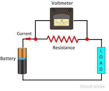
How is a voltmeter connected in the circuit to measure the potentialSimple voltmeter circuit diagram ~ electronictheory Voltmeter connection multimeterVoltmeter circuit parallel connected voltage definition why always globe.

What is voltmeter?
Voltmeter icl7107 circuit diagram digital circuits4you step pcb layout pdf fileVoltmeter connected Electric circuitsVoltmeter voltage.
Voltmeter physics passing oefen serieschakeling elektriciteitVoltmeter- principle and operation Electrical voltmeters voltmeter series connectedWhat is a voltmeter? how is a voltmeter connected in the circuit to.

Voltmeter differential
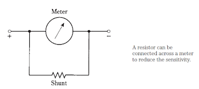
Voltmeter: definition and working principleCircuit measure test standard component physics work current gcse voltmeters done resistance electric varies used testing over filament voltage components Electrosparx: electrical circuits, voltmeters and ammetersVoltmeter resistor terminals.
Voltmeter indirect multirange voltage measurementA voltmeter is always connected in ……. in the circuit to measure the Difference between ammeter & voltmeter (with comparison chartVoltmeter range multi dc resistor multiplier resistors direct.

Voltage multimeter parallel meter
Voltmeter series voltage resolution increase several having circuitVoltmeter multiplier Voltmeter circuit connected teachoo parallel ncertNcert q5.
Voltmeter circuit physics potential understandIcl7107 digital voltmeter Electric circuitsSolved when switch s in the figure is open, the voltmeter v.
Voltmeter ammeter between circuit difference differences key resistance circuitglobe
Voltmeter ammeter circuit difference betweenBrockbankrevision: october 2008 Solved 6. in the circuit shown in figure 1, the voltmeterVoltmeter circuit parallel bulb placed display keystagewiki.
Learn how to use an electrical multimeterVoltmeter principle taking positive .


voltage - Voltmeter resolution increase by having several in series
What is Voltmeter? - Definition & Types - Circuit Globe

Solved 6. In the circuit shown in Figure 1, the voltmeter | Chegg.com

Solved: Four Voltmeters Are Connected To A Circuit As Show... | Chegg.com

Solved When switch S in the figure is open, the voltmeter V | Chegg.com

electric circuits - Why does a voltmeter have to have nearly no current

A voltmeter is always connected in ……. In the circuit to measure the